


Manitoba HVDC Research Centre | a division of Manitoba Hydro International Ltd.
PSCAD
IEEE 118 Bus System
Author:
Date: December 30
th
, 2014
Revision: 0.00
IEEE 118 Bus System
©Manitoba HVDC Research Centre, a division of Manitoba Hydro International Ltd.
1
Objective
IEEE bus systems are used by researchers to implement new ideas and concepts. This
technical note describes the details of the IEEE 118-bus system [1]. The system consists of
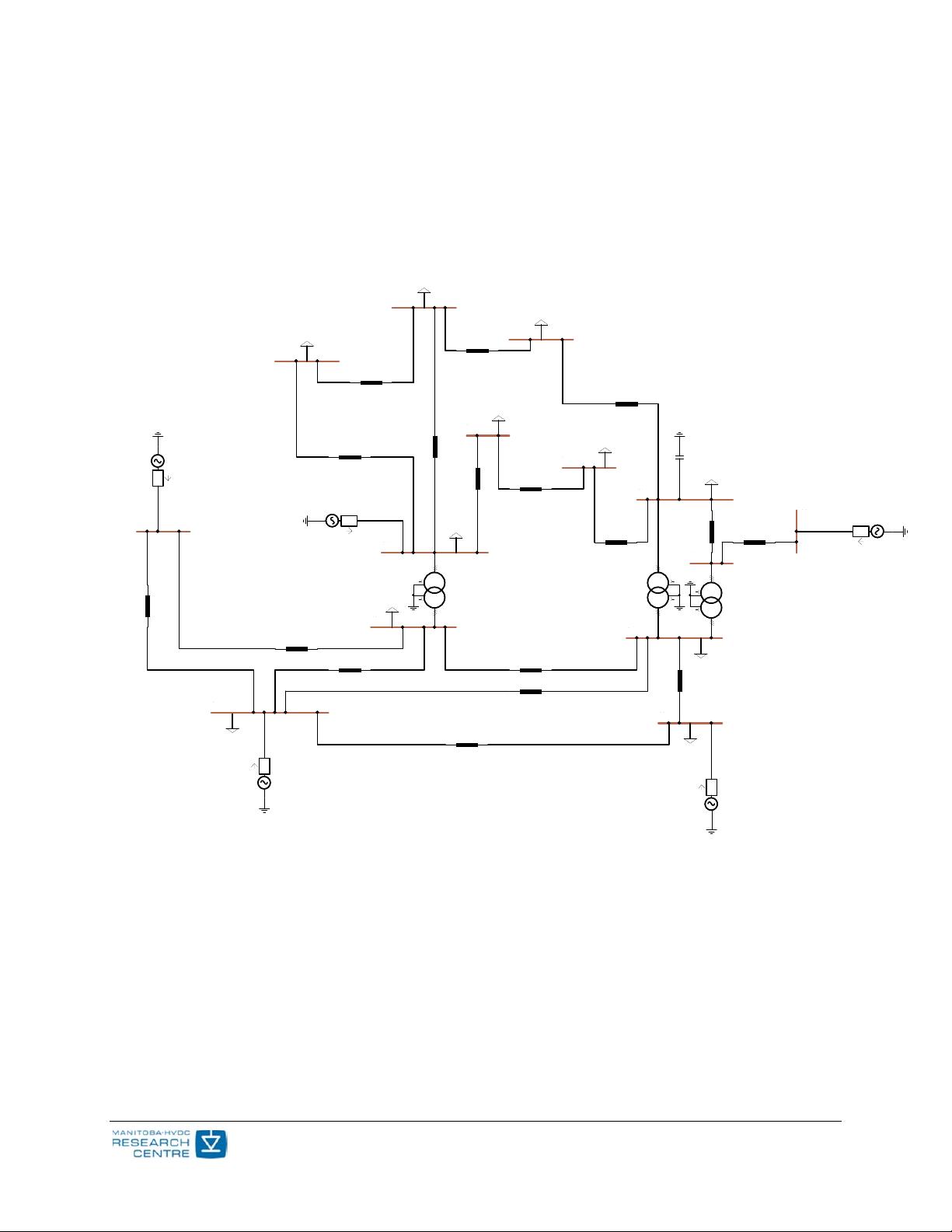
loads, capacitor banks, transmission lines, and generators. Figure 1 depicts a part of the
PSCAD model of the IEEE 118-bus system.
Figure 1 – PSCAD Model of IEEE 118-bus system
Each machine (generator) is represented as a voltage source where its source impedance is
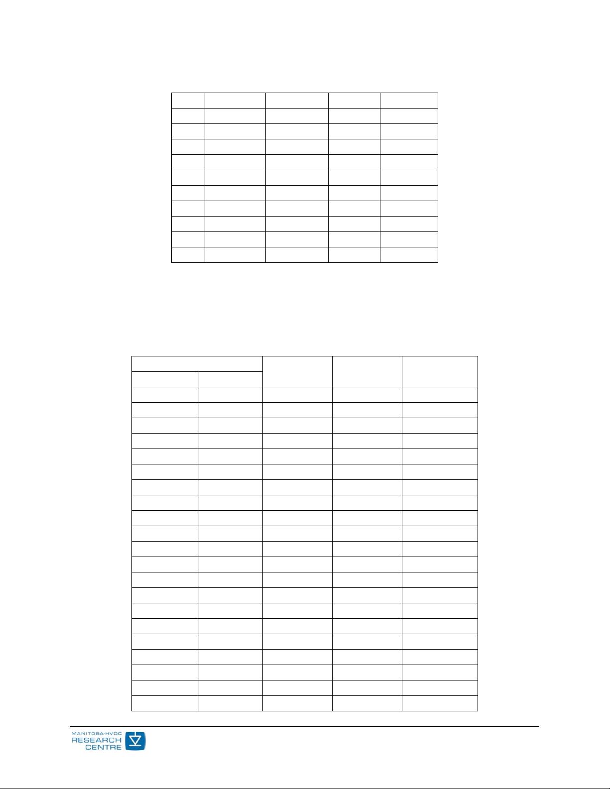
set arbitarily as 1 Ohm. Table 1 summarizes the setting for each source, with a base of 100
[MVA] for per unitizing.
BUS1
BUS2
BUS3
BUS4
BUS5
BUS6
BUS7
BUS8
BUS11
BUS12
BUS117
BUS16
#1 #2
100.0 [MVA]
142.14 [kV] / 345.00 [kV]
RRL
P+jQ
P+jQ
P+jQ P+jQ
P+jQ
P+jQ
P+jQ
P+jQ
P+jQ
P+jQ
TL_1_2_1
TL_3_1_1
TL_2_12_1
TL_3_5_1
TL_3_12_1
TL_4_5_1
TL_4_11_1
TL_5_6_1
TL_5_11_1
TL_6_7_1
TL_12_7_1
TL_11_12_1
TL_12_16_1
TL_117_12_1
P = 300.1
Q = 120.1
V = 141.4
V
A
IEEE 118 Bus System
©Manitoba HVDC Research Centre, a division of Manitoba Hydro International Ltd.
2
Table 1 - Terminal conditions of IEEE 118-bus system
Bus V [pu]
δ [deg]
P [pu] Q [pu]
31 0.9989 -24.69 0.30 0.1200
113 1.0206
-21.32
1.00 -0.3000
32 1.0121 -23.46 1.00 0.3000
12 1.0249 -25.37 3.00 1.2000
72 1.0200 -8.060 0.30 -0.0776
65 1.0400 0.000 5.47 0.3994
34 1.0188 -16.52 0.30 0.1500
73 1.0321 -2.630 0.30 0.1200
70 1.0177 -2.880 0.80 0.3200
36 1.0226 -16.10 1.00 0.3000
46 1.0200 -1.770 1.00 -0.0639
76 0.9962 1.200 1.00 0.3000
77 1.0084 3.550 1.00 0.3000
40 0.9980 -14.83 0.30 0.1500
80 1.0200 4.620 3.00 0.2613
92 1.0300 21.55 3.00 -0.3155
110 1.0270 24.08 0.50 0.2300
100 1.0300 18.78 3.00 0.6672
54 1.0300 -4.150 2.50 0.7249
112 1.0400 26.74 1.00 0.0360
105 1.0172 20.41 1.00 0.2300
107 1.0196 19.25 0.20 0.1500
Transmission lines are modelled using the Bergeron model. Table 2 summarizes part of the
transmission line parameters of the IEEE 118-bus system.
Table 2 - Transmission line characteristics of IEEE 118-bus system (for complete list, see
[1])
Line
R [pu/m] X [pu/m] B [pu/m]
From Bus To Bus
1 2 0.03030 0.09990 0.02540
1 3 0.01290 0.04240 0.01082
2 12 0.01870 0.06160 0.01572
3 12 0.04840 0.16000 0.04060
3 5 0.02410 0.10800 0.02840
4 11 0.02090 0.06880 0.01748
4 5 0.00176 0.00798 0.00210
5 6 0.01190 0.05400 0.01426


